Networking Fundamentals 1
This article is not meant to be read with 0 knowledge of the topic.
In order for two computers to communicate, they must somehow be connected to each other. Today, we take it for granted that I can buy a Lenovo laptop, and it has the ability to join the internet and communicate with your Asus PC right out of the box. Lenovo and Asus don’t have a special partnership in order to make this happen. All they have to do is build their devices such that they follow world-wide accepted protocols for communucation.
Some history
Once upon a time (1960s), two devices made by two different companies could not talk to eachother. There was no standard way to communicate between networks, operating systems, and computers. IBM was working on their own proprietary network design and OS, allowing an IBM machine to only talk to another IBM machine. Note that packet switching was starting to become a prevailent idea (1), just missing the step from theoretical to practical in order to combat the older circuit switching technology.
The International Organization for Standardization (ISO) recognized this problem, and created a template/model called (somewhat confusingly) the Open Systems Interconnect (OSI). The OSI model is simply a guide and didn’t explain the “how”.
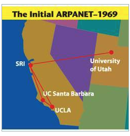
As it turned out, the OSI model wasn’t the only model proposed during the period. The U.S. Department of Defense (DoD) was also developing its own communication protocol, now known as the Transmission Control Protocol/Internet Protocol suite, or TCP/IP (2). More specifically, it was ARPA (Advanced Research Projects Agency), today known as DARPA (Defense ARPA), through partnerships with universities and various research groups, that developed the predecessor to the modern Internet. It was named ARPANET, and it was the first ever implementation of packet-switching (the year is 1969).
 https://www.historyofinformation.com/detail.php?entryid=3823 (3)
Although the initial protocol used was the Network Control Protocol (NCP), throughout the 1970’s, Vint Cerf and Robert Kahn (today known as the fathers of the Internet) researched on packet network interconnection protocols and co-designed the TCP/IP protocol suite together.
On January 1, 1983, ARPANET has officially transitioned from to the more flexible and powerful TCP/IP protocol suite, marking the start of the modern Internet. Hence, this day is considered the official birthday of the Internet!
Meanwhile, what was known as the “protocol wars” were coming to an end. As more vendors and institutions chose to go with the protocol that the DoD was backing, no one had shown a proof of concept for the OSI model.
TCP/IP vs OSI model
Today, the OSI model is just a conceptual tool, a model, which is used to diagnose systems. The networking model which we have implemented and is in direct use is called TCP/IP. Every computer which wants to talk to other computers supports and has implemented the infrastructure to support this model. Both these models have multiple functions, and so they are broken down into layers.
TCP/IP has 4 layers (from bottom to top): Network (deals with ethernet cables, and devices’ MAC addresses), Internet (IP addresses and routers), Transport (TCP/UDP), and Application (HTTP is to be used for opening a website, for example). They might be called differently depending on the source, but in reality, we prefer to use the OSI model when talking about the layers.
OSI has 7 layers (from bottom to top): Physical (ethernet cables, physical onnections), Data Link (MAC addresses), Network (IP addresses), Transport (TCP/UDP), Session (connection management, such as through website cookies), Presentation (format and display data properly), Application (user interface, such as HTTP for websites or SMTP for email).
When IT professionals talk about layers, they are always talking about the OSI layers. For example, network engineers, will refer to the Application layer as Layer 7. That’s just how it is, and for that reason it is important to learn both models.
It’s also good to know which device operates at which layers.
Layer 1 (L1) is all about cables and the physical wiring between devices which fire electrical signals at incredibly fast speeds.
A switch operates at Layer 2 (L2) because in order to transmit the data to the right port, it must know the destination’s MAC address (physical address of a device, unique to all devices). Switches have a table (called the CAM table, or “content addressable memory”) which they use to link a port with a device using that device’s MAC address. If connected to a router, devices also get a L3 address, or IP address (192.168.0.156 for example), but the switch, operating at L2, has no knowledge of the layers above it. IP addresses are invisible to the switch. It deals with the L2 addresses, namely the MAC address of devices. Finally, L2 data packets are called frames (technically they are “frames”, but sometimes network engineers refer to them as packets, which is technically what L3 data is called). (4)
The router operates at Layer 3. While the switch allows multiple users to talk to one another within the same network, it is the router which allows different networks to connect to each other. If I want to visit www.kidcoder.ca, which is on a server somewhere outside of my home network, then I must use a router in order to leave my internal network. Since www.kidcoder.ca does not have the IP address in the range of 192.168.0.1 - 192.168.0.255 (or 192.168.0.1/24), this means that it is not in the internal network, and a switch will no longer be of any help. We will need the help of a router. Your router is also called a default gateway (think of it as a gateway to the outside world), and it will probably have a local IP address of 192.168.0.1 (since it is a device on your network). This is also where L3 comes into play since we are adding a new dimension to the situation. And when L3 data is moved around, we refer to them as “packets”. (5)
Imaged below are four networks, each represented by a color. The computers on a given network are connected with each other using a switch. For a computer on one local network to communicate with a computer from another network, the signal must go through the switch and onto the personal router. Through potentially several hops of various routers (within “the Internet”), the destination router is reached, which forwards the message to the switch and onto the desired computer.
 PowerCert Animated Videos Youtube video
Switches (and hubs) are used to create networks, while routers are used to connect networks.
Notes:
1
While the circuit switching infrastructure was already in place thanks to the telephone lines, it really wasn’t clear how to build a packet switching system. Packet switching basically entails sending a message in parts, through potentially different routes, and reassembling that message in the correct order at the destination. This technology has numerous benefits over the old technology, some of which are enabling the more efficient use of existing communication channels and being faster. On the other hand, circuit switching used a dedicated communication line between two parties. This meant that the entire channel was busy, even if it wasn’t being used to its full capacity by the two parties.
2
It’s interesting how so many (if not all) major technological advancements have originated in the defence sector. As the Cold War was escalating, in 1957, the USSR managed to send the first man-made satellite into orbit, called Sputnik (which is the russian word for “satellite”). The US followed suit a year later. That same year, President Dwight D. Eisenhower created the National Aeronautics and Space Administration (NASA), a federal agency dedicated to space exploration. ARPA (today known as DARPA) was also created that year. It was in 1961 that Yuri Gagarin of Russia became the first person to orbit the Earth inside Vostok 1 (which is the russian word for “East”). At this point, no one knew the implications of the space race, but the US was planning for the worst case scenario: a nuclear attack. And hence developing an efficient communication protocol from coast to coast was important.
3
The four initial participants involved were: UCLA (University of California, Los Angeles), the Stanford Research Institute (SRI), UCSB (University of California, Santa Barbara), and the University of Utah.
4
As a sidenote, ARP (Address Resolution Protocol) also operates on L2. ARP is used to map IP addresses to MAC addresses. So when device A wants to communicate with device B (both on the same network), it only knows it’s IP address. In order for devices to communicate within the same network, MAC addresses must be used. Device A will first check it’s ARP cache to see if it knows the MAC address of device B. If it is not found in the ARP cache of device A, then device A will broadcast (through the switch) an ARP message asking all devices on the network “who has IP address XX.XX.XX.XX, and if that’s you, send me your MAC address”. Device B will respond to the ARP message and send device A it’s MAC address, thus allowing for communication between the two devices.
Note that the “broadcast” message occurs when the destination MAC of a message is FF:FF:FF:FF:FF:FF.
The same concept exists in the Network Layer when dealing with IP addresses, where a “broadcast address” is that which has all host address bits as 1. This means that for a given network address, the broadcast address is the largest possible IP address (similar to how all F’s is the largest possible MAC address).
For example, if we have 172.16.0.0/12, this means that the first 12 bits (the first octet and a half) represent the network portion. Converted to binary form, we have 10101100.00010000.00000000.00000000, and the corresponding broadcast address would be 10101100.00011111.11111111.11111111, which is the same as 172.31.255.255.
5
If I want to visit www.kidcoder.ca, I don’t send a ping or something to the server. I use my browser. I type in the domain name. When I press enter, the query goes to my DNS, or Domain Name Server, which is found on my internal network. Same as before, if it’s my first time communication with the DNS server, I must first get it’s MAC address. To get it, an ARP message is sent. Once the DNS server returns the IP address for www.kidcoder.ca (that’s the DNS response), my computer can send it out to my switch, which forwards it to the router, which then goes out to the kidcoder.ca’s router (probably through many different paths), which responds to the HTTP GET request and returns the webpage back to my computer.
Sources:
https://en.wikipedia.org/wiki/Protocol_Wars https://www.usg.edu/galileo/skills/unit07/internet0702.phtml#:~:text=January%201%2C%201983%20is%20considered,Protocol%20(TCP%2FIP)](https://www.usg.edu/galileo/skills/unit07/internet07_02.phtml#:~:text=January%201%2C%201983%20is%20considered,Protocol%20(TCP%2FIP)) [https://www.history.com/topics/cold-war/space-race](https://www.history.com/topics/cold-war/space-race) [https://en.wikipedia.org/wiki/ARPANET](https://en.wikipedia.org/wiki/ARPANET) [https://en.wikipedia.org/wiki/Network_Control_Protocol(ARPANET)